• Guys, we've spent considerable money converting the Les Paul Forum to this new XenForo platform, and we have ongoing monthly operating expenses. THE "DONATIONS" TAB IS NOW WORKING, AND WE WOULD APPRECIATE ANY DONATIONS YOU CAN MAKE TO KEEP THE LES PAUL FORUM GOING! Thank you!

Troubleshoot Fender(ish) amp?

reswot

Active member
Joined
Jan 22, 2004
Messages
3,295
Hey, all...

I built a BF Vibrolux Reverb clone last week and am having a couple of issues with it.

It (mostly works) and sounds good, but there are two issues. The first is that it's just not as loud as it should be. It's not as loud as my blackfaced 70 Deluxe Reverb, but close. The second is that the vibrato doesn't work.

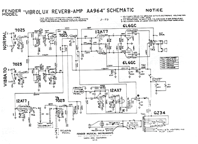
I've checked all of the voltages from the schematic and layout and, except for one tube (the vibrato tube), they check out within spec -- just a few volts higher than the schematic, due to higher wall voltages. The only discrepancies are on the plates of V5: the schematic shows 350v on pin 1 and 405v on pin 6. I get 360 on pin 6 and 415 on pin 1. I actually don't under stand how the voltages could be what the schematic says, as both plates are fed by the same B+, and pin 6 is fed from a 10M resistor and pin 1 is fed from a 220K resistor; I would expect that voltage would be dropped more at pin 6, correct?

Besides that, the voltages are correct everywhere.

I can see the light flashing on and off in the roach, so I don't suspect that's the problem. I'm getting continuity at all of my connections. I've changed the vibrato tube several times (a new Tung-Sol, two NOS GEs, and one old RCA longplate); none made a difference. Besides the light, I can sometimes hear a faint thump when I switch on the vibrato. The footswitch is turning on the circuit.

Any advice on where to look?
 
Last edited:

LeonC

Well-known member
Joined
Aug 30, 2002
Messages
809
Some thoughts...

Which schematic are you working from? AA964? AA270?

How's the bias check out?

On my AA964 schematic...it shows the opposite of what you mentioned -- mine's got 405V on pin 6 and 350V on pin 1.
 

reswot

Active member
Joined
Jan 22, 2004
Messages
3,295
You're right; I typed it backward.... I'm using the AA964 schematic.

I've got lower voltage on pin 6, which seems logical to me.... I've got higher voltage on pin 1, which again seems logical.

I edited the post above.

fenderVibrolux_Reverb_aa964-Schematic.gif
 

reswot

Active member
Joined
Jan 22, 2004
Messages
3,295
I've tested with everything at 1 (no zero) and with vol/treb/bass at 4/5/3. I don't really see a fluctuation in the voltages -- maybe a volt or two, but that's within normal variance.

The schematic shows the "B" voltage coming to the plate resistors as 405; I get 425 because of higher wall voltages. It shows the voltage after the dropping 220K resistor for pin 1 to be 350, but the voltage on pin 6 after the drop across the 10M resistor to be 405 (i.e. no drop). That makes no sense to me.

I'm getting 360-ish on pin 6 and 415-ish on pin 1, both of which seem more reasonable than the schematic would suggest, given my B voltage.

I still get no vibrato effect. The light pulses, the footswitch activates it, and I can hear a faint thump. The intensity pot has a good ground and everything looks to be connected right. The only odd thing is these voltages and -- as I say -- they actually make sense to me....

I've tried multiple tubes... Could it be a tube socket issue?

Where else should I look?
 

LeonC

Well-known member
Joined
Aug 30, 2002
Messages
809
I'm trying to think of the things I'd do.

I've suggested twice that you check the bias on your power tubes. Have you checked the bias? What is it reading? i.e., milliamps?

I'd TEST the ACTUAL value of every resistor in the bias and oscillator circuits too. Make sure they're within spec. Also, carefully test their value when the amp is turned on.
 

reswot

Active member
Joined
Jan 22, 2004
Messages
3,295
The tubes are a nice, close set: 44.1 and 43.4 ma at 422 V.

I'll get a check of all of the resistor in the circuit...

It could be the photo resistor in the roach, I guess. I've got another one I could try, but they're such a PITA to get to...
 

sonar

New member
Joined
Jan 10, 2003
Messages
3,589
The only discrepancies are on the plates of V5: the schematic shows 350v on pin 1 and 405v on pin 6. I get 360 on pin 6 and 415 on pin 1.


This needs to be sorted.

Any chance we can get some pics?
 

reswot

Active member
Joined
Jan 22, 2004
Messages
3,295
Sure... NOTE: the bypass cap for V4 is installed backward in this pic. I actually noticed it as soon as I took the pics and switched it around. I just didn't retake the pics...

You can see the laptop with a layout; the iPad with the schematic is just out of view.

I didn't have a 100 ohm resistor for the NFB, so I put two 47s in series.

IMG_1413.JPG

IMG_1416.JPG

IMG_1417.JPG

IMG_1418.JPG

IMG_1419.JPG


The vibrato doesn't work, but the amp is quiet as hell, so that's good, at least! :)
 

LeonC

Well-known member
Joined
Aug 30, 2002
Messages
809
I think you've got the wrong bias resistor (2200) on V5 pin 3. Should be 2700, yes?
 

reswot

Active member
Joined
Jan 22, 2004
Messages
3,295
damn... That's probably it. I'll switch that out today.

Thanks.
 

sonar

New member
Joined
Jan 10, 2003
Messages
3,589
Do you have continuity from pin 6 to the roach and 10M resistor?

Any chance you have the opti-coupler backwards?
 

reswot

Active member
Joined
Jan 22, 2004
Messages
3,295
Fixed it...

The damned roach leg had broken at the eyelet, but I couldn't see it...

Changed the 2K7 resistor to a 2K2 and resoldered the roach and now I'm in business.

Thanks, everyone. It's usually the obvious (but hidden) stuff, huh? I'd checked continuity to the pot, but hadn't checked the roach, itself.
 

reswot

Active member
Joined
Jan 22, 2004
Messages
3,295
Well, that was frustrating... The leg wire was just sitting there, so my meter was probably touching it every time I checked; it just wasn't connected to the eyelet and I couldn't see...
 

sonar

New member
Joined
Jan 10, 2003
Messages
3,589
Good news!

A Vibrolux Reverb was my first really good amp. Still have it.

I've used this forum to troubleshoot two of my builds, and both amps are still my main and backup band amps. The LPF at its finest.
 

reswot

Active member
Joined
Jan 22, 2004
Messages
3,295
The roach is the optocoupler/light dependent resistor and led that controls the vibrato since these don’t use a bias wiggle. It’s an LDR and LED in shrink wrap, so it looks like a bug.

I’m glad it’s working.

Thanks to all.
 

LeonC

Well-known member
Joined
Aug 30, 2002
Messages
809
Fixed it...

The damned roach leg had broken at the eyelet, but I couldn't see it...

Changed the 2K7 resistor to a 2K2 and resoldered the roach and now I'm in business.

Thanks, everyone. It's usually the obvious (but hidden) stuff, huh? I'd checked continuity to the pot, but hadn't checked the roach, itself.


Awesome. Yah, it's really hard for one person to diagnose his own work sometimes, after you've been staring at it for hours...it becomes so easy to miss tiny details.

The "modern roaches" are all pretty much garbage, IME.

Really glad you got it sorted out. Your build looks really great overall. Nice work! May you enjoy it in good health for many years. :salude
 

reswot

Active member
Joined
Jan 22, 2004
Messages
3,295
Thanks for the compliments on the build. It's just a matter of taking time. I can't believe I kept missing that disconnected wire.

I've yet to find a modern roach that I like. I had to replace the one in my DR not long ago and it pained me to have to do it, but the old one was just shot...
 
Top