

njschneider2
New member
- Joined
- Jul 16, 2018
- Messages
- 7
New to this forum, so apologies if SG posts are not allowed here! I tried registering on Everything SG but they said I was a robot and I can't access the site anymore.
Anyway, I'm trying to replace the quick connect harness in my 2017 Gibson SG Standard T with Emerson pots and orange drop caps. I got everything soldered and connected, but now the max volume is much lower than my other guitars, and there is a hum unless I complete the ground (touch the pickups, strings, bigsby, etc). So I must have done something wrong.
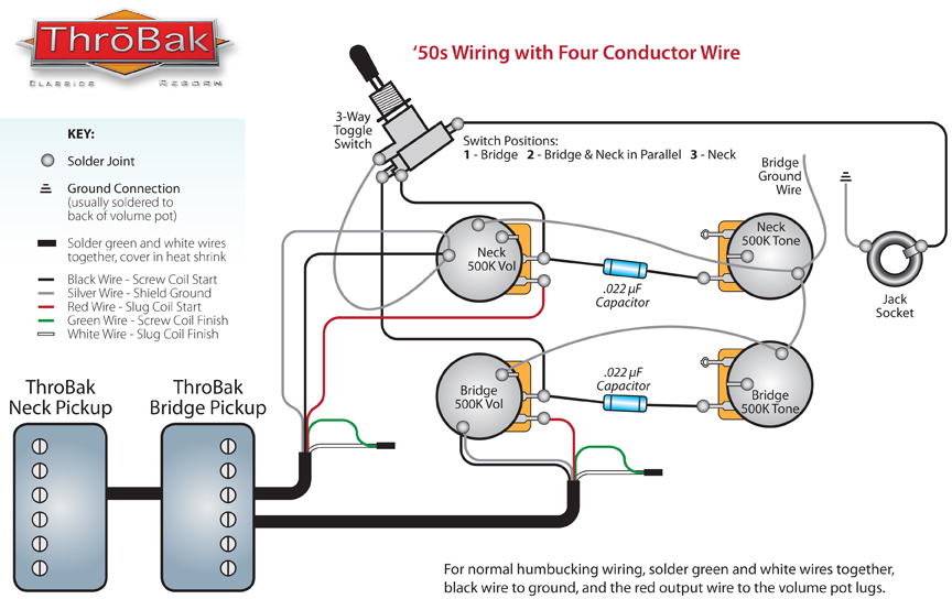
I tried finding a wiring diagram for the 57 Classic pickups that are in the SG but without much success. I thought I saw a diagram that said: Red hot, green and white taped off, black + bare to ground. So that's what I did. But I feel like I saw other people tape off the black and white wires and solder green + bare to ground.
I feel like the low volume tells me something is grounded that shouldn't be. I've also grounded the bare wire from the guitar cavity.
Any guesses as to what is wrong? I'll try to post some pictures later, but for now I was just hoping to get a general diagram for how the 4 conductors should be connected.
Anyway, I'm trying to replace the quick connect harness in my 2017 Gibson SG Standard T with Emerson pots and orange drop caps. I got everything soldered and connected, but now the max volume is much lower than my other guitars, and there is a hum unless I complete the ground (touch the pickups, strings, bigsby, etc). So I must have done something wrong.
I tried finding a wiring diagram for the 57 Classic pickups that are in the SG but without much success. I thought I saw a diagram that said: Red hot, green and white taped off, black + bare to ground. So that's what I did. But I feel like I saw other people tape off the black and white wires and solder green + bare to ground.
I feel like the low volume tells me something is grounded that shouldn't be. I've also grounded the bare wire from the guitar cavity.
Any guesses as to what is wrong? I'll try to post some pictures later, but for now I was just hoping to get a general diagram for how the 4 conductors should be connected.